During the course of providing training for our customers who purchase a GNSS mapping system, we often get asked, “How do I get my AutoCAD drawing into TerraSync?”
Depending on how AutoCAD is used, the drawing could have a known spatial reference or it could have an arbitrary coordinate system defined as the lower left corner of the drawing as “zero-zero.” Since GNSS doesn’t understand what zero-zero is, we have to transform that drawing to a known coordinate system or get the GNSS mapping system to understand the arbitrary reference system used by the drawing.
Since there are two ways to create successful communication between these two systems, you first must decide that either 1) you want to assign a known spatial reference to your AutoCAD drawing, or 2) you want your GNSS system to adopt the arbitrary coordinate system that the AutoCAD drawing is using.
The first option is the easiest and probably the one that most users would choose. In order to get your drawing to into TerraSync as a background file using a known coordinate system, we must study the drawing to determine if there are points (locations) in the drawing that can be recognized by going out into the field and occupying those points.
Examples of this are road intersections or individual features like survey control points or property corners. Typically you can find several points on the drawing that you can also occupy with your GNSS mapping system. We recommend that you find at least 4 or 5 of these locations to produce a good result.
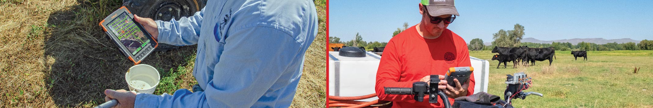
Take your GNSS mapping system into the field and occupy as many locations as you found, being careful to hold the antenna over the point and collect the necessary number of positions (10-30) to insure an accurate observation.
Back in the office, download the file and go through the differential correction wizard to post process the data, making sure to use a base station as close to the project site as possible that also has the correct reference datum along with a high integrity index. View the estimated accuracy summary to insure you got acceptable results based on the specifications of your GNSS system and your project accuracy requirements, if any.
Now it’s time to export the corrected COR file to a DXF file. We recommend that you use the “Sample Legacy AutoCAD DXF Setup with Blocks.” We also recommend that you choose a State Plane coordinate system for the zone in which your project lies. An example of an export setup if the project is near Portland, Oregon might be: “US State Plane 1983, Zone Oregon North 3601, NAD 1983 (Conus), MSL Geoid 12A (Conus), International Feet.”
There are a variety of coordinate systems you could choose, but a Cartesian coordinate system closely mimics the arbitrary system native to AutoCAD.
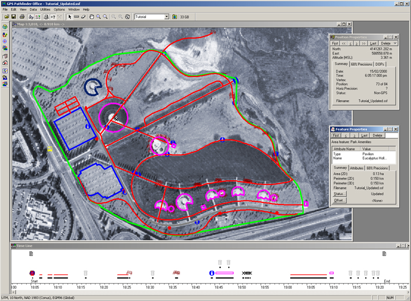
Now, you can open or Import the DXF file into a new AutoCAD drawing. The next step is to merge the AutoCAD drawing you want to put into TerraSync with the new drawing you just created by visually lining up the point locations you observed in the field with the corresponding locations in your original drawing. By doing so, you have just assigned known coordinates to an AutoCAD drawing that was accurate to itself, but had no idea where it was in the world. It is now ready to be sent to TerraSync Professional or Centimeter Edition as a background file.
The end result is that the user can go out into the field and walk around on top of the AutoCAD drawing to a high degree of accuracy if they are receiving real time corrections.
The alternative method of getting the drawing into TerraSync is preferred under these circumstances: Let’s say you own a mining claim. You have assigned a custom coordinate system to an AutoCAD drawing representing your claim. You would like to use the drawing in the field, but the GNSS mapping system does not understand that custom system. Pathfinder Office provides the tools to create that custom system using “Create a Local Site.”
Like the previous method, you must go out into the field and observe on at least 4 or 5 points. The Create a Local Site utility supports up to 20 observations, so you can collect more points if you want to. The key to remember is that any points you choose to observe must also be visible in the AutoCAD drawing.
Bring the data file into the office and apply corrections using the Differential Correction Wizard. Use the same criteria you employed in the first method to obtain accurate results. Make sure to change the display settings in Pathfinder Office to a State Plane System. Naturally, choose one that matches the physical location of you mining claim.
Before you can proceed to the Create a Local Site utility, you must have a list of the coordinate values for each point in your AutoCAD drawing that corresponds to the points you observed in the field with your GNSS mapping system.
While displaying the corrected file in the Pathfinder Office map windows, go to Options, then Create a Local Site. Click on the Add button and type is a name for the first Vector. It’s not important that you give it a name unless it’s a recognizable feature that you may wish to identify later. There’s check mark in the box, “Pick from Map.” Click on one of the points in the map window, then type in the coordinate value of the corresponding point from your AutoCAD drawing. Make sure to check your entry so you haven’t transposed any numbers. Click “Add.”
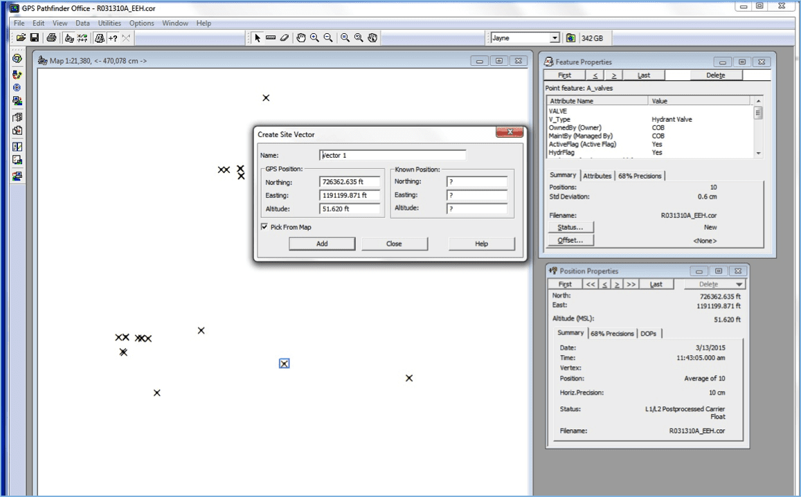
Continue to pick points from the map and then enter the coordinates from the AutoCAD drawing until you have entered them all (up to 20). Click on “Close” and then “Solve.”
The 2D and 3D residuals will be displayed. You want to see very low numbers, which would indicate the software was able to do a very accurate “best fit” solution between the two coordinate systems. If you see a residual that show a very high number, you can delete that observation and then solve again to see if you get acceptable results. The dialog will report that the values in the residual columns are displaying feet or meters, whatever you chose. Acceptable residuals will be determined by your ability to accurately observe on points in the field, the intrinsic accuracy of the AutoCAD drawing, your ability to choose the correct feature in the AutoCAD drawing, and the accuracy specifications of your GNSS receiver.
Finally, click on Create Site. You now have an opportunity to name the new coordinate system that you just created. Once named, you can send it into TerraSync as a custom coordinate system.
After connecting your GNSS receiver to Pathfinder Office, click on Send, Add, Custom Coordinate System. Choose the new system, then Transfer All. You will be asked to send the Geoid Model you choose associated with your custom system. Accept it and click OK.
Warning: this will wipe out all other coordinate systems in TerraSync, except for Latitude, Longitude, but they can be restored easily be re-installing TerraSync onto your handheld.
The end result of this method will be to see features in your custom coordinate system while in the field. It will also allow you to collect new features in that system for use in Pathfinder Office and in AutoCAD. This method is the least-used of the two because most users want to assign a known coordinate system to an AutoCAD drawing.
If you have any questions about these methods, we are always happy to help.
Solutions
Frontier Precision provides world-class solutions for a wide variety of industries using leading products, training, technical services and more.


Products
Technical Services
If you require customized technical services and training, please contact Frontier Precision at 800-359-3703 or reach out to a local Frontier Precision location.
Training and Events
Frontier Precision offers affordable regularly scheduled certified training classes, online eLearning, webinars, as well as custom training options to meet your specific training needs.
About Frontier Precision
Contact Frontier Precision